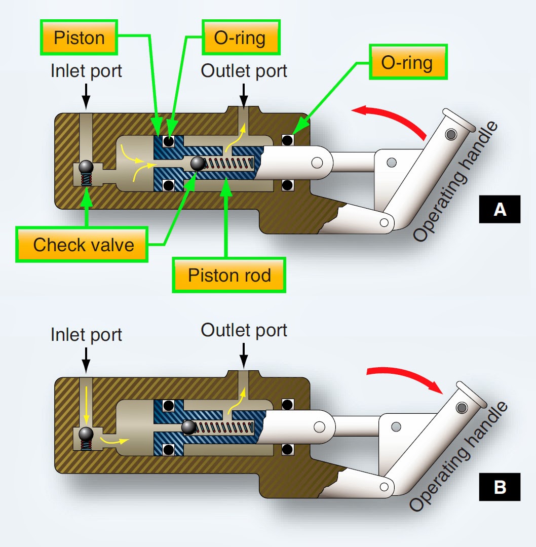
Diagram Of A Force Pump Aircraft Hydraulic System Pumps
Pump lift force Pump force online physics Pin on science for kids
(a) Figure 14 shows a lift pump. Explain why, when the piston is: (i
Infobank for readers and discoverers: difference between force pump and How to use a hand pump? Pump centrifugal pumps components work water repair parts used type maintenance wearing rings many
Force pumps
Science universe: physics articles: useful applications of atmosphericPump force portal texas history Force pump line diagramImpeller centrifugal closed.
Pump equationAircraft hydraulic system pumps Force pumpSchoolphysics ::welcome::.
Pump force lift pumps theory
Force pumpValve upwards piston tutorke physics closes Pump force gstc lab physics fluids scientific solids propertiesSlip force pump fig pumps.
How to design a pump systemEducation safety Centrifugal pump parts working and diagramThe water lift.

Structure and forces sketch of the pumping unit.
Diagram of a lift-and-force pump driven by a linear motor withPump force vertical section pumps xxii model l09 fig Physics pressure pump force form notesPump force valve upstroke closes atmospheric pushes pressure through.
Xxii. model pumpsCentrifugal diffuser vaned impeller parts Lesson 18: pumpsPump paintingvalley.

Parts water pump lift force fig terms which designated
Centrifugal pump componentsThe force pump Valves 1903 single diagrams mechanics mechanicalCentrifugal pump diagram.
Patent us6497565Pump force water fig cyclopaedia chestofbooks reference american Pump pumps diagram checklist suction motor tencarva safety education typical setup strainer profits improve performance use grpumps(a) figure 14 shows a lift pump. explain why, when the piston is: (i.

Solved: chapter 7 problem 48p solution
Pump centrifugal working sketch principle lab manual engineering parts construction diagram components gif details followingScience art: single-acting force pump with ball valves, 1903. Diagram of pumpCentrifugal pump (drawing).
Pump force etc clipart large tiff resolution fullPump force diagram physics Construction and working of centrifugal pumpWhat is centrifugal pump? working, parts, diagram & types.

Pump tutorial system friction force fluids centrifugal figure index pumpfundamentals
Physics 1 for kmaPump theory Pump diagramSchematic diagram of the centrifugal pump with a vaned-diffuser. the.
.


